
0. What a rack PDU does
A rack PDU takes one high-capacity circuit — from utility, a UPS, or a generator — and distributes it to every device in the cabinet. Basic units just split power; intelligent units also measure it, report it over the network, and let you switch individual outlets remotely.
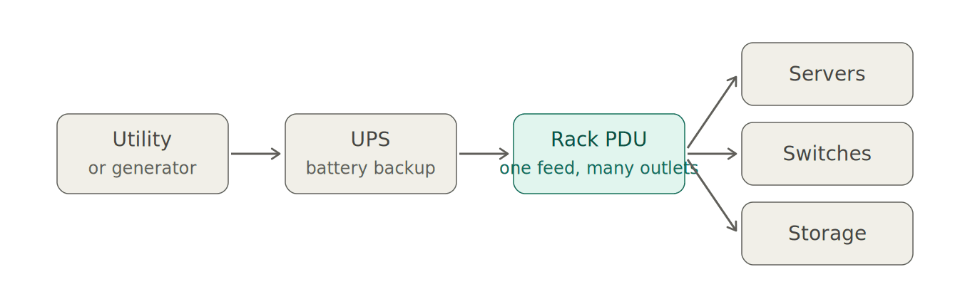
PDU vs. power strip. A power strip splits an outlet. Rack PDUs offer defined electrical ratings and rack-mounting options; connector types, monitoring and switching vary by model. Select equipment listed for the intended installation.
1. Start with the load, not the PDU
Every PDU decision traces back to one number: how much power the rack will actually draw. Get that right and the rest of the spec falls out of it.
Nameplate vs. real draw. A server's nameplate rating is the maximum the power supply can pull, not what it draws in service. Actual input varies with configuration and workload. Sizing to nameplate over-buys the PDU, the circuit, and the upstream distribution. Sizing to a guess under-buys and trips breakers.
How to get the number:
- Best: measured data from an existing metered PDU, UPS output, or the servers' own BMC/iDRAC/iLO power telemetry.
- Good: the vendor's power calculator for each configured system (Dell, HPE, Cisco, Supermicro all publish them) at the expected utilization.
- If measurements are unavailable: use a documented worst-case estimate for the configured equipment and review it with facilities. Do not size a circuit using an arbitrary fraction of nameplate.
Add up every device in the rack — servers, storage, switches, and anything else with a cord — and note whether each has one or two power supplies.
Growth headroom. Plan for the rack you'll have in 3–5 years, not the one you're racking today. A 20–30% growth allowance is an example planning range; choose headroom for the actual deployment and failure scenarios. A PDU with headroom costs a little more once; a PDU replacement costs a rack outage.
2. Voltage and phase: the decision that shapes everything else
The PDU's input determines its capacity ceiling, its plug, the circuit the electrician runs, and which outlets it can offer.
| Input | Typical use | Approx. kW at 80%, PF = 1 |
|---|---|---|
| 120V, 20A single-phase | Network closets, low-density racks | ~1.9 kW |
| 208V, 30A single-phase | Light-to-medium racks | ~5.0 kW |
| 208V, 30A three-phase | Standard enterprise racks | ~8.6 kW |
| 208V, 60A three-phase | Dense compute, virtualization hosts | ~17.3 kW |
| 415V/240V, 30A three-phase (wye) | High-density, hyperscale-style deployments | ~17.3 kW |
| 415V/240V, 60A three-phase (wye) | GPU / AI racks | ~34.5 kW |
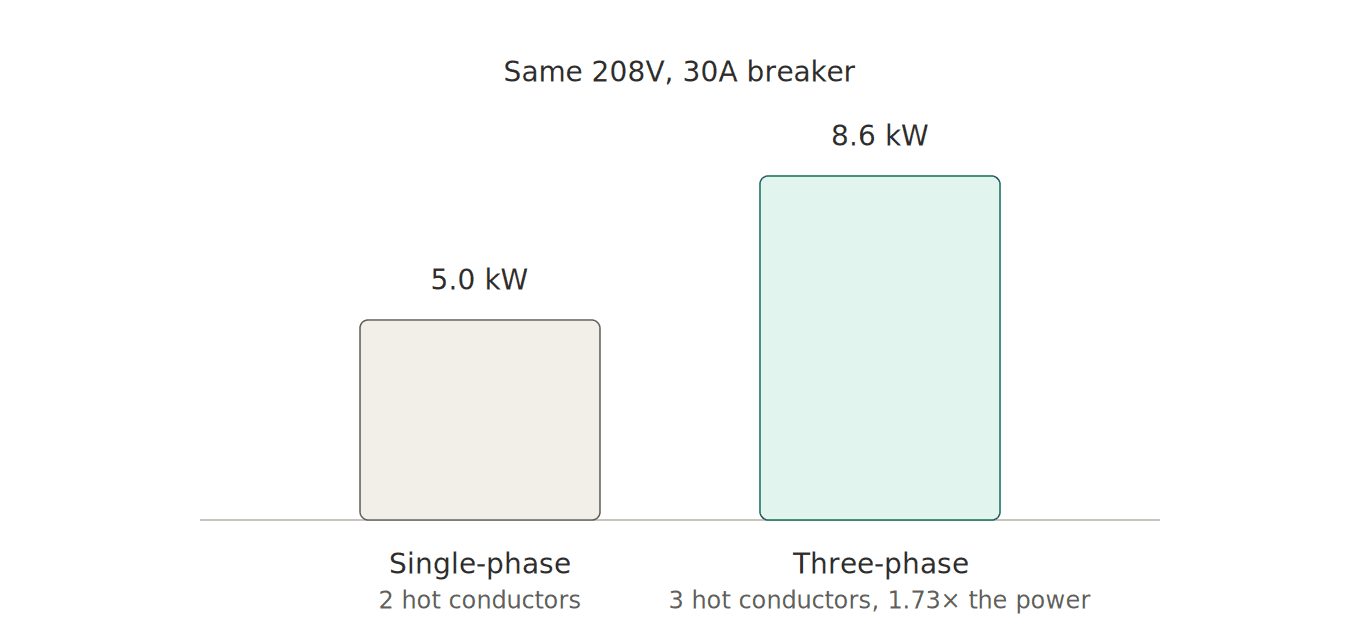
Why 208V over 120V. Higher voltage means lower current for the same power, which means smaller conductors, less heat loss, and more capacity per circuit. Check every device’s input range. Use a voltage supported by the facility and all connected equipment.
Why three-phase. Three-phase delivers roughly 1.73× the power of single-phase at the same amperage, over one cable and one breaker. For higher-density racks, compare available single- and three-phase circuits with facilities. It also lets you balance load across phases, which matters upstream at the panel and UPS.
415V/240V wye. Line-to-neutral is 240V, which can suit compatible 240V equipment; verify each device’s rated input range. Common in new builds and any facility designed around high density. Check that your upstream distribution supports it before speccing it.
3. Amperage, derating, and the 80% rule
For the common North American 80%-rated continuous-load case, a 30A circuit permits 24A continuous and a 60A circuit permits 48A. The applicable limit depends on the equipment listing, complete circuit and locally adopted requirements. Have facilities confirm the installation rating; 100%-rated assemblies require different treatment.
Distinguish nominal input current from the published continuous current. If a data sheet already states a derated usable capacity, do not apply the 80% factor again. The lowest applicable input, bank, outlet, cord or upstream limit governs.
Sizing formula (80%-rated example): These expressions use nominal circuit current. Three-phase calculations assume balanced loading and line-to-line voltage. The table assumes power factor 1; otherwise volts × amps gives apparent power in VA, not real watts.
- Single-phase: kW ≈ V × A × 0.8 × power factor ÷ 1000
- Three-phase: kW ≈ V × A × 1.732 × 0.8 × power factor ÷ 1000 (V = line-to-line voltage)
Worked example. A rack of 12 dual-PSU 1U servers measured at 450W each, plus two ToR switches at 150W each, is 5.7 kW today. With 25% headroom the design load is ~7.1 kW. A 208V/30A three-phase PDU (8.6 kW) covers it. A 208V/30A single-phase PDU (5.0 kW) does not — it is below both the present 5.7 kW load and the 7.1 kW design load.
4. Redundancy: A/B feeds and how to size for them
Dual-corded equipment gets one PSU on an "A" PDU and one on a "B" PDU, each fed from an independent upstream path. If either path fails, the other carries the full rack.
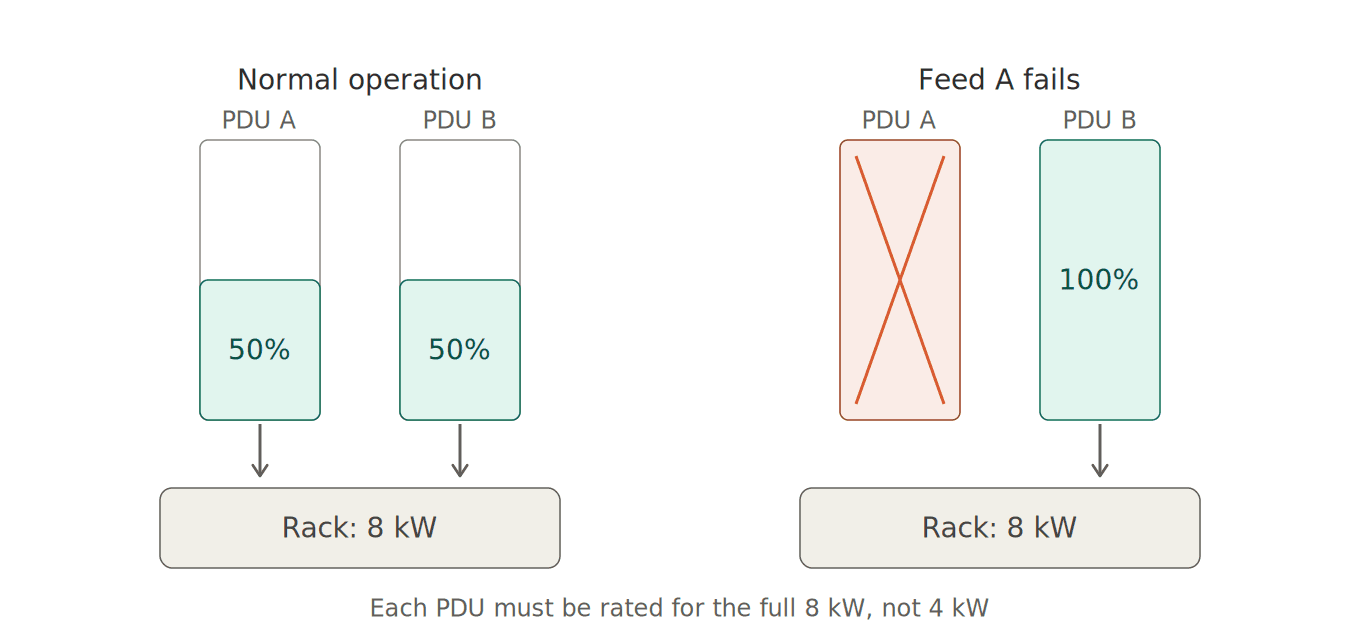
This is the sizing trap. Under normal operation each PDU carries about half the load. When one fails, the survivor carries all of it. Each PDU therefore must be sized for the entire rack load, not half. Two 8.6 kW PDUs on an A/B pair support an 8.6 kW rack, not a 17 kW rack.
Run the surviving-PDU scenario at the design load and confirm it stays within the published continuous rating of the entire surviving path. Metered or monitored PDUs make this easy to verify; basic PDUs mean you're trusting the spreadsheet.
Single-corded devices (many switches, some appliances) break the model. Options are an automatic transfer switch (ATS) rack unit ahead of the device, or accepting that device as a single point of failure.
5. Outlets: type, count, and mix
IEC C13 vs. C19. C13 outlets are rated to 10A (15A in NA-listed products) and cover the vast majority of servers and network gear. C19 outlets are rated to 16A (20A) and serve high-draw devices — blade chassis, large storage arrays, GPU servers, big modular switches. Most racks want a mix; a common split is 30–36 C13 plus 6 C19 on a 0U vertical unit.
Count. Total every cord in the rack, add 20–30% spares, then check that the outlet count matches. Running out of outlets at 60% of the PDU's power capacity is a common and annoying failure.
Locking outlets. Cords vibrate loose. Locking C13/C19 outlets (or sleeved cord-retention systems) prevent a bumped cable from becoming an outage. Strongly recommended for any rack that gets serviced regularly.
Combination outlets. Some newer PDUs offer outlets that accept either C14 or C20 equipment plugs. Useful when the mix is unknown at spec time.
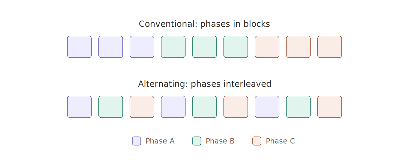
Alternating phase (three-phase PDUs only). Conventional layout puts each phase on a contiguous block of outlets, so balancing load across phases means routing cords up and down the rack. Alternating-phase layout puts phase A, B, C on adjacent outlets — distribute the actual loads across the phases and verify phase and bank currents. Adjacent alternating outlets can simplify cable routing, but do not automatically balance unequal loads. Worth specifying on any three-phase PDU in a dense rack.
NEMA outlets. Only if you have 120V-only legacy equipment or gear with molded NEMA 5-15 cords. Otherwise standardize on IEC.
6. Form factor and mounting
0U vertical. Mounts in the rear channel of the cabinet, consumes no rack units, and puts outlets directly beside the equipment they feed. The default for any rack over ~20U of populated gear. Confirm the cabinet has 0U mounting provisions and that the PDU length fits — 42U and 48U cabinets take different PDUs.
1U / 2U horizontal. Mounts in the rack rails. Right for shallow network cabinets, wall-mount enclosures, or racks where the rear channel is already taken by cable management or a second PDU pair.
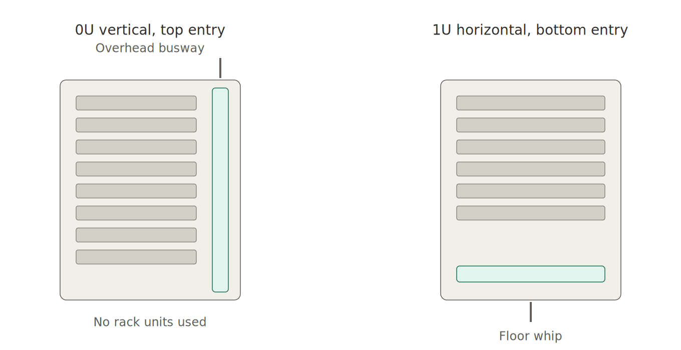
Input cord. Note the cord length and whether the input plug should exit the top or bottom of the PDU. Overhead busway feeds want top-entry; raised-floor whips want bottom-entry. Getting this wrong means an ugly service loop or a cord that doesn't reach.
Input plug. Must match the receptacle the electrician installs. Common North American choices: NEMA L6-30P (208V/30A single-phase), NEMA L21-30P (208V/30A three-phase wye), NEMA L15-30P (208V/30A three-phase delta), Hubbell CS8365C (208V/50A three-phase), IEC 60309 pin-and-sleeve (60A and up, and the standard for 415V). Agree on this with facilities before ordering — it's the single most common reason PDUs sit in a box.
Input plug reference. These are selection references, not wiring instructions. Match the manufacturer’s voltage, current and conductor configuration to the installed supply.
| Plug | Voltage | Amps | Phase | Notes |
|---|---|---|---|---|
| NEMA 5-15P / 5-20P | 120V | 15 / 20 | 1Ø | Straight-blade; closets and small racks only |
| NEMA L5-20P / L5-30P | 120V | 20 / 30 | 1Ø | Twist-lock 120V |
| NEMA L6-20P / L6-30P | 208/240V | 20 / 30 | 1Ø | The most common enterprise single-phase input |
| NEMA L14-30P | 125/250V device rating | 30 | Wiring-specific | Verify supply, neutral and PDU outlet voltages; do not infer them from connector shape |
| NEMA L15-30P | 208V | 30 | 3Ø delta | Three-phase, no neutral |
| NEMA L21-30P | 120/208V | 30 | 3Ø wye | Three-phase with neutral; mixed 120/208V outlets possible |
| Hubbell CS8365C | 208V | 50 | 3Ø delta | Common on 50A three-phase PDUs |
| IEC 60309 (pin & sleeve) | 208V or 415V | 30 / 60 / 100 | 1Ø or 3Ø | Standard for 60A+ and for 415V/240V wye |
| IEC C14 / C20 | 100–240V | 10 / 16 | 1Ø | Inlet-style; PDU fed from a UPS or another PDU |
Outlet reference
| Outlet | Rating | Typical use |
|---|---|---|
| IEC C13 | 10A (15A NA) | Servers, switches, most 1U/2U gear |
| IEC C19 | 16A (20A NA) | Blade chassis, large storage, GPU nodes, core switches |
| Locking C13 / C19 | Same | Any rack that gets serviced; prevents accidental disconnect |
| NEMA 5-15R / 5-20R | 120V, 15 / 20A | Legacy 120V equipment with molded cords |
| NEMA L6-30R | 208V, 30A | Feeding a downstream PDU or a single high-draw device |
7. Intelligence: how much visibility do you need?
Capability matrix. Typical capability groupings; verify the exact model. Automatic transfer is a separate capability and does not imply monitoring or switching.
| Tier | Power distribution | Local display | Remote monitoring (unit) | Remote monitoring (outlet) | Remote outlet switching | Built-in A/B redundancy |
|---|---|---|---|---|---|---|
| Basic | ● | |||||
| Metered | ● | ● | ||||
| Monitored | ● | ● | ● | |||
| Switched | ● | ● | ● | ● | ||
| Metered-by-outlet | ● | ● | ● | ● | ||
| Switched + metered-by-outlet | ● | ● | ● | ● | ● | |
| Metered ATS | ● | ● | ● | ● | ||
| Switched ATS | ● | ● | ● | ● | ● |
When each tier makes sense
| Tier | Use it for |
|---|---|
| Basic | Lab racks, non-critical closets, cost-driven builds |
| Metered | Verifying load balance and headroom at install; no remote needs |
| Monitored | Any production rack. This is the practical floor for a data center. |
| Switched | Remote or lights-out sites, colo, anywhere you'd otherwise dispatch someone to power-cycle a box |
| Metered-by-outlet | Chargeback, capacity planning by device, efficiency and PUE programs |
| ATS (metered or switched) | Racks with single-corded equipment that still needs A/B protection — the ATS takes two inputs and fails over automatically |
Things to check on any networked PDU: SNMPv3 support, integration with your DCIM or monitoring stack, whether the management controller is hot-swappable (so a controller failure doesn't require a power-down), whether environmental sensors (temperature, humidity, door contact, leak) are supported and priced separately, and whether two units can be linked so an A/B pair shares one network connection and one login.
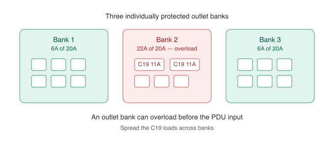
Branch circuit protection. Many higher-current PDUs divide outlets into protected banks. Consult the exact model’s protection diagram and ratings. Check the bank layout against your outlet plan — a bank is typically 16–20A, so two C19 devices on the same bank can trip it while the PDU as a whole is nowhere near full.
Vendor naming. Every manufacturer labels these tiers differently — one vendor's "Smart" is another's "Monitored," and "POPS" means metered-by-outlet. See PDU intelligence tiers: a cross-vendor decoder for the mapping.
8. Common mistakes
- Sizing to nameplate and buying a 60A PDU for a 6 kW rack.
- Sizing A/B pairs to half the load each.
- Speccing the PDU before confirming the input receptacle with facilities.
- Running out of C19 outlets, or running out of outlets entirely, well before running out of power.
- Choosing basic PDUs for production racks and then having no way to see load balance or headroom.
- Ignoring input cord entry direction and cabinet height.
- Skipping locking outlets on racks that get touched.
9. FAQ
How many kW can a 30A PDU deliver? Depends on voltage and phase. 120V single-phase: ~2.9 kW. 208V single-phase: ~5.0 kW. 208V three-phase: ~8.6 kW. 415V/240V three-phase: ~17.3 kW. These examples assume 80% continuous loading and power factor 1.
Do I need three-phase? Compare the design load against the circuits available at your facility. At the same line-to-line voltage and current, balanced three-phase provides about 1.73 times the apparent power of single-phase.
Should each PDU in an A/B pair carry half the rack? No. Each must be sized for the full rack load, because either one has to carry everything when the other path fails.
Can a PDU monitor temperature and humidity? Monitored, switched, and outlet-metered PDUs typically accept an environmental sensor (temperature, humidity, sometimes door contact and leak). Sensors are usually sold separately.
What's the difference between metered and monitored? Metered shows load on a local display. Monitored adds a network interface so you can see it remotely, set alarms, and feed it to DCIM.
Do I need C19 outlets? Only for devices with C20 cords — blade chassis, large storage arrays, GPU servers, some core switches. Check your cords before assuming.
Can I plug one PDU into another? An IEC inlet alone does not authorize cascading. Follow the PDU and upstream equipment installation instructions and applicable facility requirements. Confirm that the proposed connection is permitted and remains within every upstream rating.
10. Put your specification together
Record the design load, redundancy, facility voltage and phase, input connector, outlet counts, cabinet dimensions and monitoring requirements. Check the published continuous rating of each candidate PDU, its outlet banks and the complete upstream circuit.
Start with capacity · Browse the PDU catalog · Ask Matrix for configuration help
Technical references
Power and PDU selection fundamentals — Eaton · PX technical specifications — Raritan